
Teaching Tech 3D Printer Calibration
Useful? Considering supporting me:

This page serves as a companion for this video: 3D printer calibration revolutionised - Step by step to better print quality
It aims to make calibrating your 3D printer as easy as possible. If you find it helps you and you would like to say thank you, here is a donation link: PayPal.me
Special thanks to my Patrons for suggesting this video, helping define the contents and testing/proofing.
Watch the video and then work through each tab. I have created a custom gcode generator to assist in making testing towers. This used to be a laborious process and beyond the skills of many users. Other times pre-sliced gcode was used from the internet, but it is impossible to have gcode available for every printer configuration. Until now!
Every attempt has been made to ensure this is safe but ultimately there always is risk in running pre-sliced gcode from the internet. Preview the gcode in your slicer or Gcode.ws and print at your own risk.
Only print this gcode when you are present, alert and capable of stopping the printer in case of emergency.
Validation has been built into the forms to only allow sensible min and max values, however this is not foolproof.
The gcode generated by this page has the following general characteristics:
To be compatible, your printer should have a miniumum bed size of 100 x 100mm. The largest print is 85x 95 x 30mm.
To ensure there are no underlying problems with the frame or mechanical components of the 3D printer.
Any time the frame or mechanical components have been disassembled or replaced.
Basic spanners, Allen keys, etc.
It would be easy to use the techniques elsewhere on this page to try and fix problems that were actually caused by a problem with the physical components, so we will eliminate this possibility first.
Many of these procedures are covered in this video: Complete beginner's guide to 3D printing - Assembly, tour, slicing, levelling and first prints
Move around the machine and check all fasteners. Crucial ones include those on the print head gantry such as those that hold the hot end on.
If your printer has a motion system based on V-roller wheels riding on V-slot extrusions, check they are properly tensioned. Each location will have one eccentric nut. This can be twisted to either add or remove tension on the wheels.
If the wheels are too loose: Wobble will be present in the assembly, which will show in the print as surface artefacts.
If the wheels are too tight: The assembly will be too tense, which will wear the V-rollers prematurely.
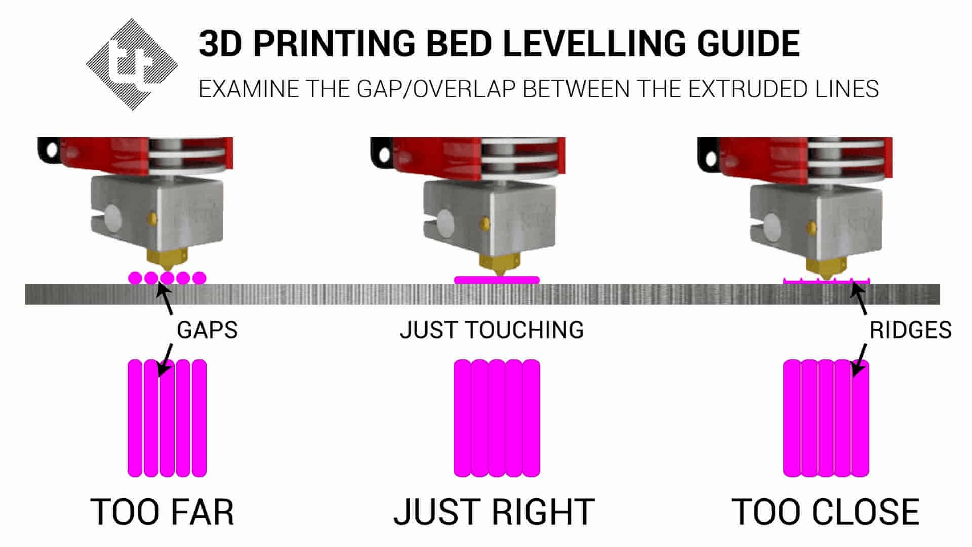
Probably the most essential part of setting up your 3D printer. Most new users will trip up on this. If you have ABL, this includes making sure your Z offset has been set and saved. My method is included in the above video and this diagram is a handy reference:
If your printer has PTFE tube, such as a bowden tube setup for the extruder/hot end, it is essential to make the tube is fully inserted and seated in the coupler. Also ensure the coupler is properly tightened. You may wish to use a small retaining clip on the coupler to prevent the tube working loose: Creality PTFE clip by morfidesign.
It is worth heating up the nozzle and pushing some filament through to see if it is exiting the nozzle properly. If the diameter is inconsistent or the extruded plastic shoots to one side, it may indicate a partial blockage in the nozzle that will be a pain in the future. It is also worth checking if the nozzle is properly tightened. Only do this when it is hot, or you may break it.
Ensure all belts are properly aligned and tensioned sufficiently. Also check the grub screws are tight on the pulleys that connect the belts to the stepper motors.
Check all fans are spinning freely. This includes but is not limited to: mainboard cooling fan, heat sink fan, part cooling fan, PSU fan. It can be hard to diagose if a fan is performing at less than full capacity. It may be easier to simply replace than repair if you suspect a fan is failing.
Another suitable video for seeing some of these procedures is here:
To ensure the heating of the 3D printer nozzle and bed are safe, stable and consistent.
Any time the hot end is changed, including adding/removing a silicone sock or altering part cooling fan/ducts. Any time the bed is changed, such as adding a glass/mirror plate, magnetic spring steel sheet and/or under bed insulation.
Terminal software such as Pronterface or Octoprint.
PID autotuning is quick and easy, and relates to the most potentially dangerous components of your 3D printer: the heaters. It makes sense to do it as a first step. This procedure is covered in this video: Two easy fixes for 3D printer temperature swings
In Marlin, this is a very straightforward process using M303.
In a terminal, enter the following to tune the hot end:
M303 E0 S200 U1
This will tune the hot end at 200 degrees. The S value can be altered to suit your most common printing temperature. The U1 means the result is stored to RAM and we can save it immediately to EEPROM by sending:
M500
For the bed, PIDTEMPBED must be enabled in the firmware, then the command is quite similar:
M303 E-1 S60 U1
The bed is selected with
M500
It may be preferable to have the printer as close to printing conditions as possible during these tuning procedures. That means having filament loaded and the part cooling fan on for PLA temperatures.
To establish a baseline for comparison with later tests or before modifications.
Before general calibration or before a significant modification is to be fitted.
Gcode generator on this page.
The form below will create a customised version of the XYZ 20mm calibration cube by iDig3Dprinting. It is fast to print and gives a good indication if there is any fundamental problem with the printer.
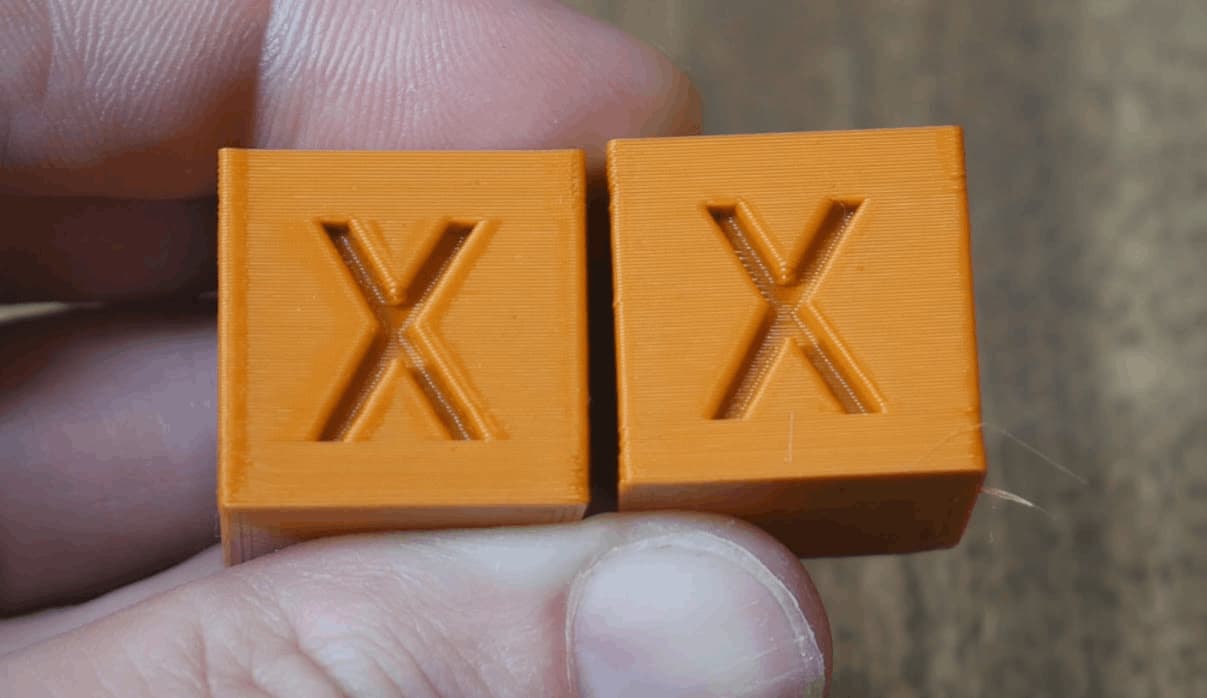
The cube should look similar to those at the top of this page. If there are no major issues, please continue to the next step. If there is a significant defect, the culprit will likely be found by working through the frame page.
To determine the correct amount of steps Marlin firmware needs to send to the extruder stepper motor for accurate movement.
Base calibration, as well as any time there has been a change to the extruder/hot end.
Ruler, permanent marker, terminal software such as Pronterface or Octoprint.
For the X, Y, and Z axes, the steps per mm is usually consistent between printers and rarely changes with modifications. As long as belts are tight and true, it rarely needs to be tuned.
For the extruder however, variations in extruder hardware and filament means it is worth properly calibrating the extruder steps per mm, or E-steps.
This can be done by sending simple gcode commands via terminal to extrude a set amount of filament, then measuring how much filament actually went through the system.
This calibration is best done with the extruder detached from the hot end, so no restriction is present on the movement. If it is convenient, you can partially disassemble the printer so the output of the extruder is open and the filament exits in free air. If this is inconvenient, the process below aims to minimise restrictions by extruding very slowly and with a slightly higher temperature. The results from this should still be reliable.
Firstly, we need to know the existing E-steps value. To find this, enter:
M92
If you only receive an ok message from this, alternatively you can look for the M92 line after entering:
M503
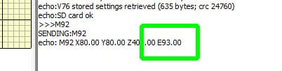
M92 is used to report or set the steps per mm for each axis. M92 by itself will report the current parameters. We want to make note of the number after E, in the example below, 93.00:
Now heat up your hot end to whatever temperature you usually print with plus 10 degrees. Once the temperature is stable, enter:
G91
G91 puts the printer in relative movement mode. This means requesting 100mm of filament adds 100mm to the current position, instead of moving to the specific position of 100mm.
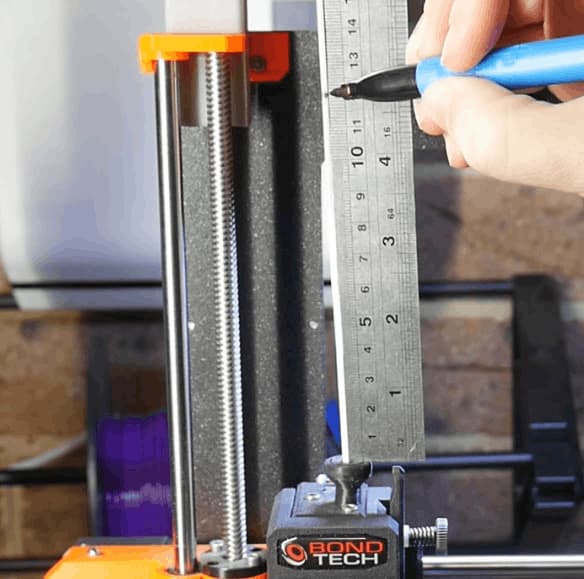
Now we take a permanent marker and put a mark 120mm from the entry to the extruder:
Next, we enter:
G1 E100 F50
G1 sends a move command to the printer, in this case asking the extruder to advance 100mm at a speed of 50mm/min.
The filament will then very slowly go through the extruder (and hot end). Once the extrusion finishes, we measure the distance between the mark and the entry to the extruder.
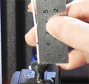
Ideally, 20mm remains, which means exactly 100mm was extruded. If your distance is anything other than this, complete the form below to calculate the correct E-steps:
Although starting a new print or power cycling will achieve this, it may be safer to put the printer back into absolute position mode after completing this calibration by sending:
G90
To determine the correct amount filament to be extruded by the 3D printer as directed by the slicer.
Base calibration, as well as any time there has been a change to the extruder/hot end.
Your favourite slicer. Accurate digital/vernier callipers (two decimal places is much more preferable to a set with only one).
Our E-steps are now correct in the firmware, so we will move on to calibrating the slicer. Each slicer has a setting to control the overall amount of filament extruded by the printer. If the flow rate is increased, more filament will be extruded. If the flow rate is decreased, less filament will be extruded.
In Simplify3D and PrusaSlicer, this is called Extrusion Multiplier. Cura calls it Flow.
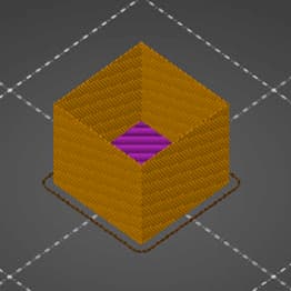
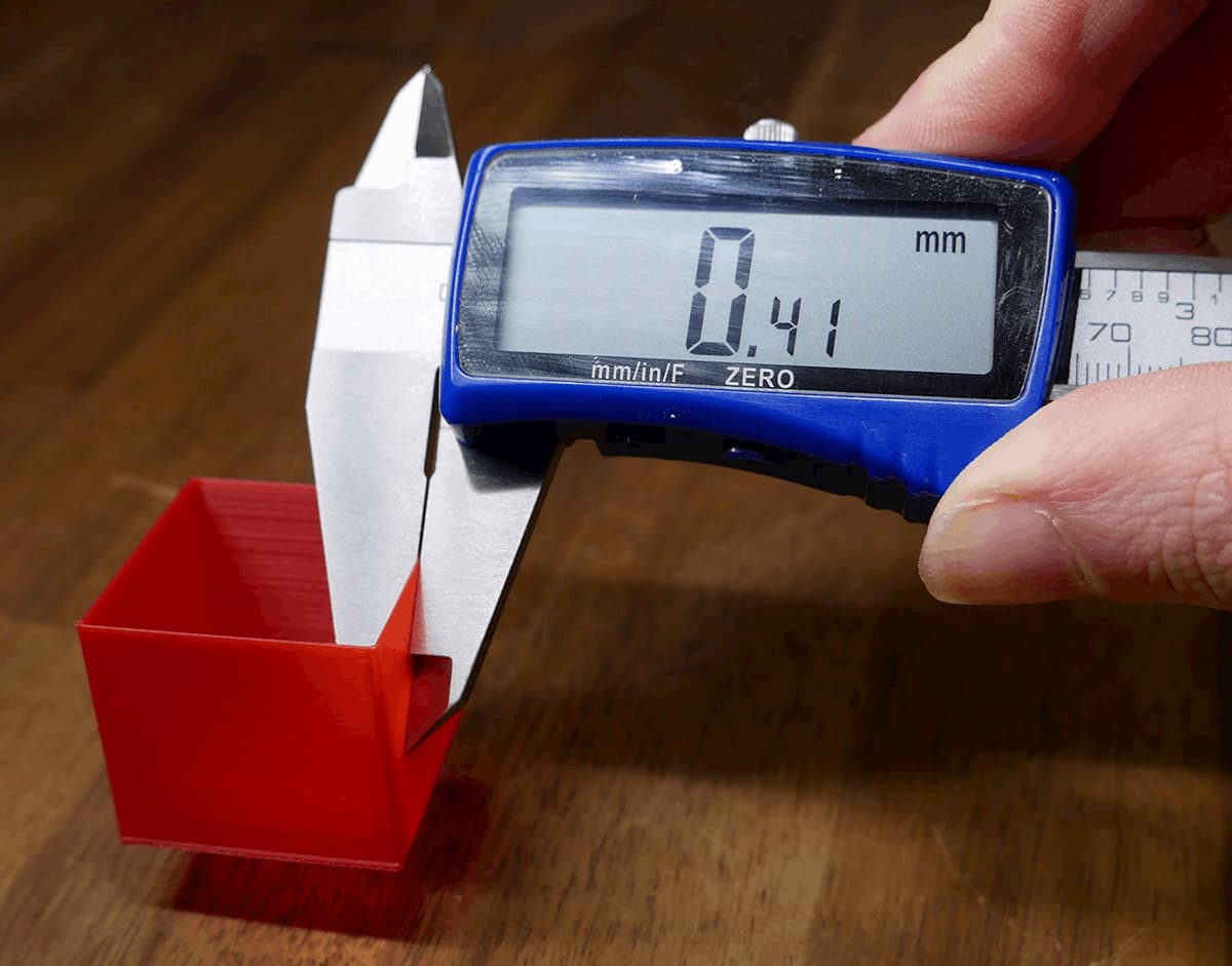
My method of determining the correct flow rate is to print a hollow, single wall cube with a specified wall thickness, then measure the actual thickness of the wall and adjust the flow rate in the slicer to suit.
Some people prefer to have multiple walls and measure them together. For example, if the extrusion width was 0.4mm with two perimeters, then you would be hoping to measure 0.8mm for the cube wall. This does introduce more variables, such as the amount of perimeter overlap, and therefore a risk of the process failing. This is why I personally prefer a single wall cube, but each to their own.
Unfortunately, I can't provide pre-sliced gcode for this process. It is vital to use gcode generated by YOUR slicer. Setting up your slicer to print the cube in the right way should be simple by following these steps:
| Step | Cura | Simplify3D | PrusaSlicer |
|---|---|---|---|
| 1. Import STL | cube.stl | ||
| 2. Turn off infill | Infill > Infill density: 0% | General settings > Infill percentage: 0% | Print settings > Infill > Fill density: 0% Also set infill to 0% on main panel |
| 3. Turn off top layers | Shell > Top thickness: 0 | Layer > Top solid layers: 0 | Print settings > Layers and perimeters > Horizontal layers > Top: 0 |
| 4. Ensure wall thickness is a known value. Substitute whatever values you like here. This example uses 0.4, which is common for a 0.4mm nozzle and 0.2mm layer height. |
Shell > Wall thickness: 0.4 | Extruder > Extrusion width > tick manual > 0.4 | Print settings > Advanced > Extrusion width > Default extrusion width: 0.4 and Print settings > Advanced > Extrusion width > Perimeters: 0.4 |
| 5. Set outer wall thickness to single extrusion | Shell > Wall line count: 1 | Layer > Outline/Perimeter shells: 1 | Print settings > Layers and perimeters > Vertical shells > Perimeters: 1 |
| 6. Set flow rate to default: 1.0 / 100% | Material > Flow: 100 | Extruder > Extrusion multiplier: 1.0 | Filament settings > Filament > Extrusion multiplier: 1 |
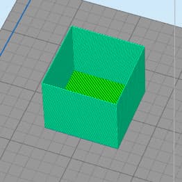
| 7. Expected result: | 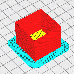 |
 |
 |
Now slice and print!
Use digital/vernier callipers to measure the outer wall thickness of the hollow cube. Take measurements in multiple places/sides and average them.
If your measurement is significantly off, the following calculator can then be used to calculate the new flow rate:
| Cura | Simplify3D / PrusaSlicer |
|---|---|
What you see with your eyes is more important than a theoretical calculation. After you have performed this calibration, please adjust the flow rate higher or lower based on what you actually see.
For example, the cube shown in the thumbnail of the XYZ 20mm calibration cube by iDig3Dprinting:
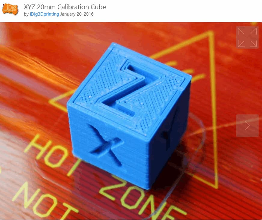
This print shows clear signs of under extrusion. There are gaps in the top infill as well as gaps between the perimeters and infill. Despite what any calibration procedure determined, the flow rate for this slicer/printer combination needs to be increased.
This article on all3DP has examples of what over extrusion looks like.
To set the correct amount of current supplied to the stepper motors of the printer. This is set with the stepper motor drivers, located on the mainboard.
If steps are being skipped/missed. If the stepper motors are too hot to touch. When significant changes are made to the motion system (e.g. heavier bed, conversion to direct drive from bowden tube).
If your 3D printer is running fine without hot stepper motors, you may skip this step.
For newer, 'smart' stepper motor drivers: terminal software such as Pronterface or Octoprint.
For older stepper motor drivers: a multimeter, small screwdriver and a spare wire with alligator clips (optional but recommended).
Setting the stepper driver current is an important step in calibrating a 3D printer, although typically the value does not need to be exact. There is a window within which the printer will operate without issue.
General methods are used on this page, but if you are after more detail on a specific driver, my stepper motor driver guide playlist may be of use.
Although we target a specific current, the following rule of thumb is the most important factor:
If the stepper motor is missing steps or you are experiencing layer shifts, the stepper current needs to be increased. This will supply more torque to the motor but also make it (and the driver) run hotter.
If the stepper motor is too hot to touch, the stepper current needs to be decreased. This will remove torque and make the motor (and the driver) run cooler.
Unfortunately, sometimes a stepper motor may be running hot and still missing steps. The following may apply in these cases:
If tuning the stepper driver current is unable to find a sweet spot, the good news is you can upgrade to a larger stepper motor easily in most cases. Nema17 steppers have the same mounting pattern and output shaft diameter, however you should still check your machine to ensure there is enough room for a longer stepper before any purchase. With all else being equal, a longer stepper motor will be capable of more torque and handling higher current.
Depending on the stepper motor driver, there are two ways of setting the current:
For older stepper motor drivers or TMC drivers running in legacy mode, the current is set by turning a trim pot screw on the top of the driver to raise or lower VREF, which in turns sets the driver current.
On TMC drivers, the current is set directly with gcode commands. This can be set in the firmware, via a terminal or by using the printer's LCD. This value should then be saved to EEPROM to stay persistent.
We will cover these one at a time below.
Setting stepper driver current accurately relies on knowing two values: the peak current that the stepper motor is rated for and the sense resistor value on the stepper motor driver.
For newer TMC drivers, the sense resistor value is already known. For older drivers, methods for determining this are seen in the following snippet. Methods for determining the stepper motor peak current are shown too:
I have covered this in detail before, so please use the embedded video below (queued to the correct time) to see how to set the VREF. The process is essentially the same for any driver.
The VREF is just a reference voltage to assist us in setting the driver current. It is used because it is much simpler to measure voltage rather than current with a multimeter. Typically these drivers have the peak/max current set.
The general steps for setting current via VREF are the same between drivers, only the VREF formula changes:
Alternatively, you can use an alligator clip wire between the red probe and the metal shaft of the screwdriver, so that a VREF reading is available as you turn the screwdriver. This procedure is shown in this snippet:
The VREF formulas for drivers I have tested are as follows:
The typical sense resistor value is 0.1. Please check your drivers to be sure.
VREF = 8 x max current x sense resistor value
Then use the video above as a guide to the process.
The sense resistor value should be 0.1. If it is:
VREF = max current / 2
The process is then the same as for A4988s as shown in the video above.
Like the TMC drivers covered in the gcode section, the current for the TMC2100 is set not as a peak, but instead as RMS. To determine RMS, divide the peak current by 1.41.
VREF = (RMS current * 2.5) / 1.77
The process is then the same as for A4988s as shown in the video above.
Like the TMC drivers covered in the gcode section, the current for the TMC2208 (legacy mode) is set not as a peak, but instead as RMS. To determine RMS, divide the peak current by 1.41.
VREF = (RMS current * 2.5) / 1.77
The process is then the same as for A4988s as shown in the video above.
There are mainly two kinds of stepper driver boards with this driver.
One has a resistor labelled R100 on the bottom, and on the other the resistor is labelled R220. Which formula you use is based off of this resistor
The process is then mostly the same as for A4988s as shown in the video above, but with the correct formula for your driver board.
R100:
VREF = max current / 2
R220:
VREF = max current * 1.1
TMC drivers connected via UART or SPI serial can easily have their current set via gcode. This is not peak current, but rather RMS (root mean square) current. Rather than the maximum, think of this as more a typical/average current, where the driver will be operating mostly. To convert the peak current from stepper motor specs to RMS, divide it by 1.41.
The current can be set in a few different ways for each driver:
These drivers should have a sense resistor value of 0.11. This is the default in Marlin, so when compiling it should already be set (X_RSENSE for the X axis, Y_SENSE for Y and so forth):
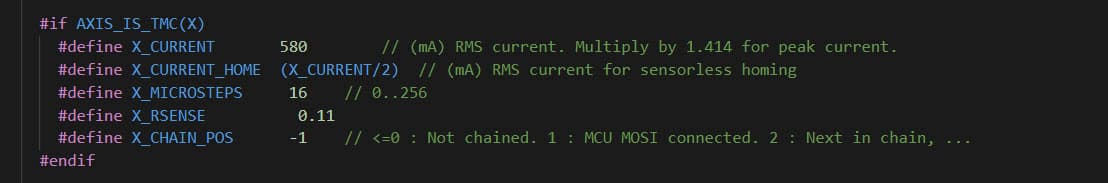
Therefore, you can set your RMS current directly in the firmware when compiling. This is X_CURRENT for the X axis, Y_CURRENT for the Y and so forth. After flashing firmware, remember that the previous value may still be stored in the EEPROM. Check your values by entering M503 in a terminal.
You can also set the RMS current via terminal with M906. Please follow the link to see the reference. An example of setting the X axis current to 680 would be:
M906 X680
Don't forget to save the value to EEPROM afterwards with:
M500
Finally, the LCD Configuration menu can be used to set the RMS current. Don't forget to save afterwards by clicking on Store Settings.
The TMC5160 is the same as the other TMC drivers apart from one important difference: the sense resistor value needs to be changed from 0.11 to 0.075 when compiling the firmware.
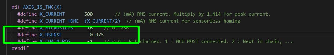
After this change is made, the same procedures apply:
You can set your RMS current directly in the firmware when compiling. This is X_CURRENT for the X axis, Y_CURRENT for the Y and so forth. After flashing firmware, remember that the previous value may still be stored in the EEPROM. Check your values by entering M503 in a terminal.
You can also set the RMS current via terminal with M906. Please follow the link to see the reference. An example of setting the X axis current to 680 would be:
M906 X680
Don't forget to save the value to EEPROM afterwards with:
M500
Finally, the LCD Configuration menu can be used to set the RMS current. Don't forget to save afterwards by clicking on Store Settings.
To set the correct parameters concerning retraction during 3D printing, including retraction distance, speed, extra restart distance and z hop.
Initial calibration, any time the hot end or extruder is changed, when trying a new type/brand of filament.
Gcode generator on this page.
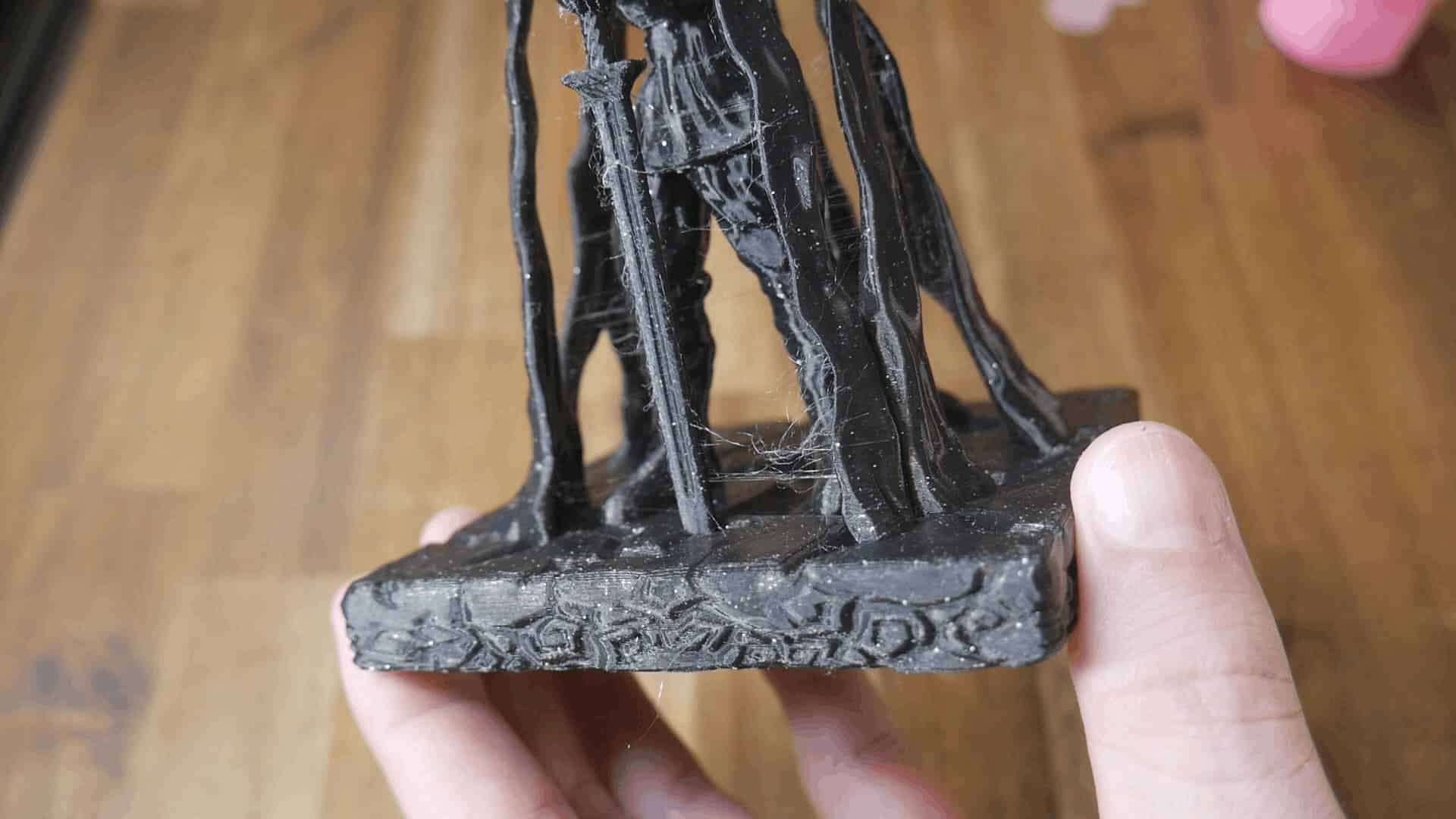
FDM works by melting plastic filament and extruding it accurately one layer at a time to build up 3D geometry. By its nature, the plastic will continue to ooze and drip out of the nozzle even when not pushed by the extruder. To combat this, our slicers use retraction, where the filament is withdrawn from the hot end, alleviating pressure and minimising ooze. When properly tuned, this has the effect of removing stringing, the unwanted oozing of plastic between two points of the model.
An example of fine stringing can be seen in the following image. It appears like cobwebs:
Temperature tuning and retraction tuning are related to each other. You could do them in either order, and it may be necessary to tune back and forth to reach an ideal result. A higher nozzle temperature will promote more oozing and stringing, whereas a lower temperature will reduce oozing and stringing.
Besides hot end temperature, there are four parameters we will be tuning relating to retraction. In the table is a description of each as well as where the setting is found in the most popular slicers.
| Retraction Parameter | Cura | Simplify3D | PrusaSlicer |
|---|---|---|---|
| Retraction distance: The length the filament is pulled away from the nozzle in mm. | Travel > Retraction distance | Extruder > Retraction distance | Printer settings > Extruder 1 > Retraction > Length |
| Retraction speed: The speed at which this filament is withdrawn in mm/sec. | Travel > Retraction speed | Extruder > Retraction speed | Printer settings > Extruder 1 > Retraction > Retraction Speed |
| Extra restart distance: The retraction distance will be reversed when the travel (non-extruding) movement is over. This is typically zero, but you can opt for extra filament to be extruded (a positive value) or less than what was retracted (a negative value). Also measured in mm. | Travel > Retraction extra prime amount | Extruder > Extra restart distance | Printer settings > Extruder 1 > Retraction > Extra length on restart |
| Z hop: The amount the nozzle lifts vertically in mm during a travel (non-extruding) movement. After this movement, the correct Z value is then restored before the filament is unretracted/primed again ready for printing. | Travel > Z hop when retracted | Extruder > Retraction vertical lift | Printer settings > Extruder 1 > Retraction > Lift z |
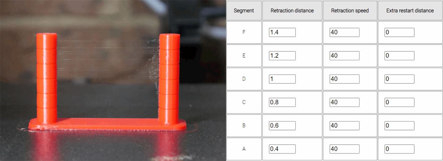
The following form will create a retraction tower to conveniently test back to back parameters in the same print. Of the three available parameters, it is best to change only one per test print. For example, keep the retraction speed and extra restart distance the same, but vary the retraction distance over each segment. Changing more than one parameter makes is hard to tell what made the difference. The print is quick, so repeat the test varying other parameters until you are happy with them all.
Here is the STL if you would like to slice a similar test yourself: retractiontest.stl
Inspect your finished print. Hopefully, there will be a clear difference between the segments that reflect the settings you entered. In the example below (Ender 3 direct drive, PLA, linear advance enabled), the retraction distance varied from 0.4 up to 1.4mm in 0.2mm increments. Segments A and B have the least stringing. Based on this, I would assume that a retraction distance of 0.4 - 0.6 is best for this printer. this is consistent with linear advance being enabled.
I would then repeat the test, setting the same retraction distance for each segment and instead altering the retraction speed to dial that in. A third test could then take place to test extra restart distance.
If you would like to be able to customise additional parameters for a retraction test, Prahjister has made a great tool: Retraction Calibration Tool. It has a higher degree of difficulty due to needing more parameters but is ultimately more powerful.
To set the ideal printing temperature for the hot end for a given filament.
Initial calibration, any time the hot end is changed, when trying a new type/brand of filament.
Gcode generator on this page.
For this calibration, we are only concerned with the temperature of the hot end, not the bed. The bed temperature will need to be matched to any given filament, and once a good value is found, you will generally stick with it.
Instead here we are tuning the temperature at which the filament is extruded. There is no universal temperature for a given filament. Variations in heater blocks and thermistor placement dictate this.
A higher nozzle temperature should result in stronger parts, particularly interlayer adhesion. Part surface may be shinier. The filament will be softer so ooze and stringing may be increased, and some surface detail potentially lost, especially on overhangs. A hot end temperature too high may damage parts of the assembly such as the internal PTFE tube.
A lower nozzle temperature should result in weaker parts, particularly interlayer adhesion. Part surface may be duller. The filament will be firmer so ooze and stringing may be reduced, with good surface detail, especially on overhangs. A hot end temperature too low can cause the hot end to jam.
Temperature tuning and retraction tuning are related to each other. You could do them in either order, and it may be necessary to tune back and forth to reach an ideal result.
The following form will create a temperature tower to conveniently test back to back parameters in the same print. There are five segments to vary the temperature. Generally the lowest temperatures would be at the start of the print (segment A) and the increase up to the highest by the top of the print (segment E).
Your 3D printer firmware will have a minimum hot end temperature extrusion is allowed and a maximum hot end temperature for safety. Make sure to keep within these boundaries to avoid errors.
Here is the STL if you would like to slice a similar test yourself: temperaturetower.stl
Inspect your finished print. Hopefully, there will be a clear difference between the segments that reflect the temperatures you entered. In the example below (Ender 3 direct drive, PLA, linear advance enabled), the hot end temperature varied from 185 to 225 in 10 degree increments"
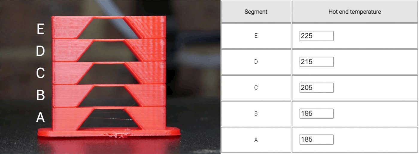
For the first layer, there was some extruder clicking as the extruder struggled to push the filament through the cooler nozzle. As expected, surface becomes more glossy as the temperature increases. What was unexpected, was surface rippling either being more prominent or at least more obvious as the temperature went up. Underhangs and bridges all look good on this test.
My previous hot end temperature was 200 degrees for this printer, but I will consider lowering it to 190 degrees after this test.
You may also wish to conduct some destructive testing to evaluate part strength. In many cases this is more important than the appearance of the part.
To find the right compromise between printing speed and quality, specifically related to surface artefacts such as ghosting.
Initial calibration, when significant changes are made to the motion system (e.g. heavier bed, conversion to direct drive from bowden tube).
Terminal software such as Pronterface or Octoprint.
Gcode generator on this page.
We set a feedrate or movement speed in our slicer, but the printer does not instantly reach these speeds. Like a motor vehicle, it needs time to accelerate. If the distance of the movement is short, it may not even have time to reach the specified speed. This can determined with the handy acceleration calculator, available on the Prusa website.
Complementary to acceleration we have jerk, replaced by junction deviation in newer versions of Marlin. These settings have differences, but both are essentially responsible for making sure the printer does not come to a complete stop between each movement, but rather decelerates an appropriate amount depending on the angle of the next 'corner'.
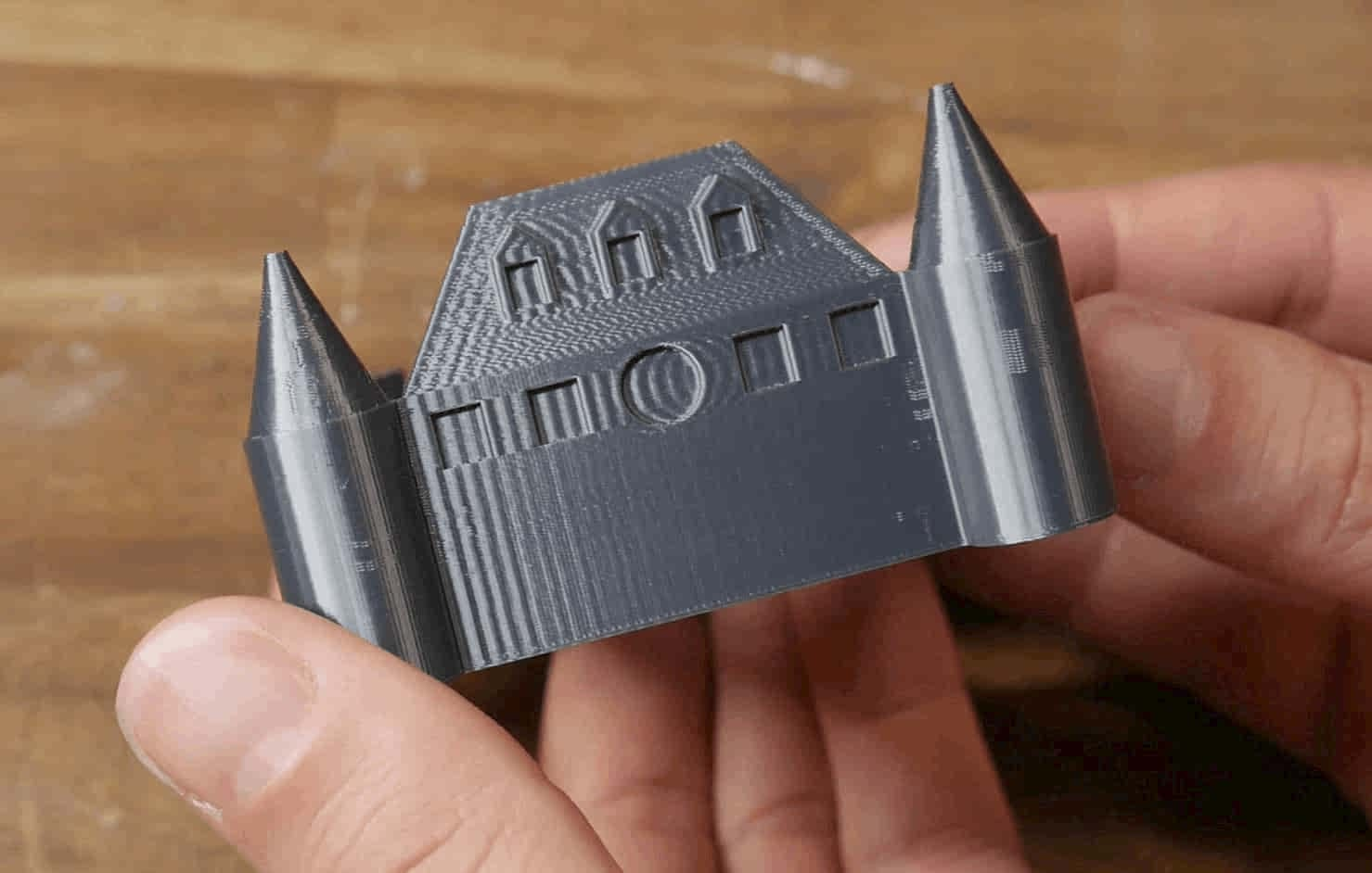
We will be tuning both of these parameters with another tower. The aim is to have a reasonably fast print time without inducing excessive ringing/ghosting. An example of bad ghosting is seen below. The features of the model are repeated across the surfaces due to vibration of the printer components:
I have previously made a detailed video guide on this subject, complete with many diagrams explaining the concepts. The tuning process depicted will be improved upon here with an easier to use calculator and custom gcode generator below.
Higher acceleration and jerk will result in a faster print time, as the printer reaches top speed faster and maintains a higher speed when corning. This is harder on the printer, and may result in reduced lifespan of components and the need for more regular maintenance. It also introduces more surface defects such as ringing/ghosting.
Lower acceleration and jerk will result in a slower print time, as the printer reaches top speed more gradually and corners at a lower velocity. This is easier on the printer, with potentially increased component lifespan and less need for regular maintenance. It reduces surface artefacts such as ringing/ghosting, unless it is far too conservative, in which case it may introduce bulging in corners.
One strategy is to calculate the fastest your 3D printer can move while extruding cleanly, set this feedrate in the slicer, and then tune acceleration to meet this speed. If you are not interested in printing as fast as possible, skip to the next section.
This part of the guide and calculator is adapted from Martin Pirringer's tutorial. Please consider supporting him and his robotics team through paypal or you can also donate to team 1989 through their Team 1989 Web Site
The following calculator will assist you in determining the maximum feedrate your printer/extruder/hot end is capable of.
We will now produce an acceleration tower to conveniently test back to back settings in a single print. If you would like to slice the model yourself, here is the STL: accelerationtower.stl. It should be sliced with a normal base, but hollow, no top layers and only 2 perimeters.
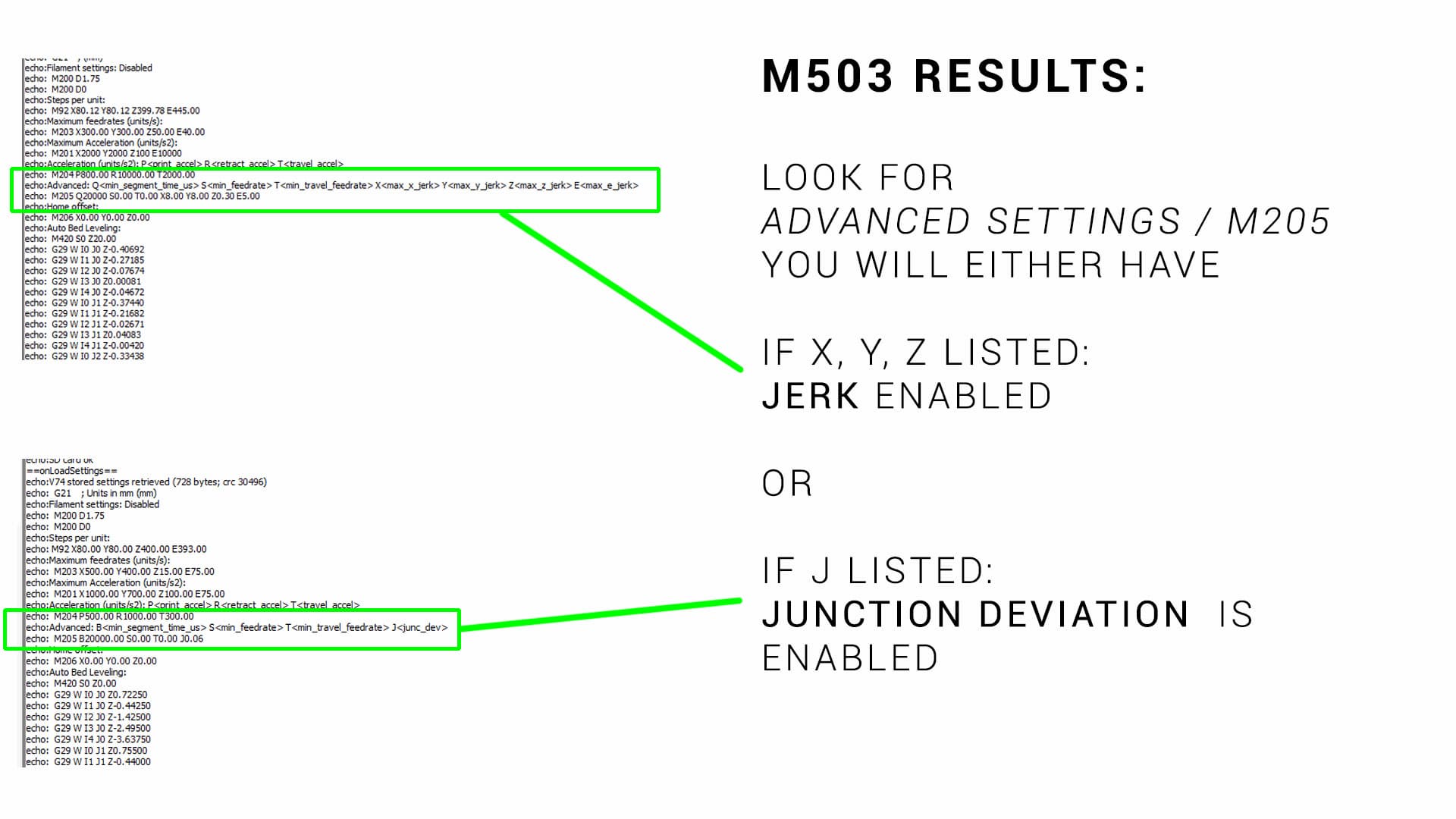
The only thing you need to know before this test is whether your firmware is set up for jerk (older) or junction deviation (newer). Entering M503 via terminal will give a list of printer variables:
The image below shows an example of each of these scenarios:
Use the following form to customise the gcode to your liking:
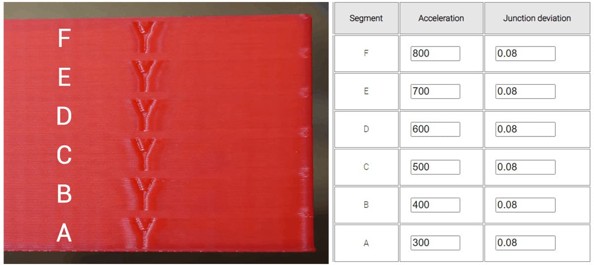
Inspect your finished print. Hopefully, there will be a clear difference between the segments that reflect the acceleration values you entered. In the example below (Ender 3 direct drive, PLA, linear advance enabled), acceleration varied from 300 to 800 in 100 mm/sec/sec increments. Junction deviation was left at the default 0.08. The difference between each segment is subtle, but there is increased ghosting around the letter Y on the higher segments. The previous value was 500, but a small increase in quality may be achieved from lowering the value to 400.
Once you have a value you are happy with, you can update with:
M204 P400
where 400 is the value of the acceleration with the best compromise based on the tower test print. We can store the value to EEPROM by sending:
M500
You would then repeat the test with all of the acceleration values locked at your preferred value for each segment, but this time varying jerk/junction deviation.
To save for a printer with jerk (with a determined best compromise of 8 for this example), we would enter:
M205 X8 Y8
To save for a printer with junction deviation (with a determined best compromise of 0.05 for this example), we would enter:
M205 J0.05
Either way, we save to EEPROM afterwards with:
M500
Each of these parameters can also be entered and stored from the configuration menu of the Marlin LCD.
To tune the timing of the extrusion with the aim of reducing swollen corners and thinner walls. This results in a more consistent extrusion and a reduction in surface artefacts.
Initial calibration, when changing the extruder/hot end (especially if changing from bowden tube to direct drive), when trying new filaments.
In a 3D printer, due to the pressure required to push the molten filament through the small opening of the nozzle, there is a small time delay from when the extruder pushes the filament to when it actually comes out the nozzle. Traditionally the movement of the extruder is matched to XY movements of the printer, so this means the start of a line will be under-extruded and the end of the line will be over-extruded. Linear advance unsynchronises the extruder movements from the XY movements, changing the timing of the extruder so the thin and thick sections are significantly reduced.
The concept and how to tune linear advance is explained in much more detail here:
Linear advance often goes by the name pressure advance. They are the same thing.
Linear advance is often not enabled by default in Marlin firmware. Therefore, the firmware must be recompiled with linear advance included. This is covered in the video above.
Linear advance is incompatible with certain stepper motor drivers. A prominent one is the TMC2208 when connected in legacy mode (as found on Creality silent boards). When connected in 'smart' mode via UART, this is not a problem.
Linear advance is not currently compatible with S curve acceleration (another Marlin feature), although it is possible to uncomment #define EXPERIMENTAL_SCURVE when adding linear advance as a work around.
Linear advance requires aggressive acceleration for the extruder and will work the motor harder. Higher current maybe required for the E driver, which will make it run hotter.
Linear advance is filament dependent. A different value is required for each filament to get the best results.
Testing for linear advance relies on the visual inspection of a single layer, therefore it is important to have your bed levelling/first layer reliable and repeatable.
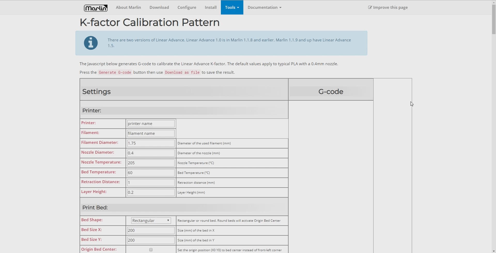
Marlin has excellent linear advance documentation and a test gcode generator already made, so there is no point recreating a competitor here. An example of how to use it is shown in the video above, and it can be found here: Marlin Linear Advance Pattern Generator
The parameter we tune for linear advance is called the K factor. The K factor relates to the amount of flex or compression in the filament and the length of the path between the extruder and hot end.
A higher K value suits a bowden tube and/or flexible filaments. This is because the filament can flex sideways in the tube in between the extruder and hot end, adding to the extrusion time delay. A good starting point for a bowden extruder is a K value of 1.0.
A lower K value suits a direct drive extruder and more rigid filaments. With these characteristics, the transfer of filament between extruder and hot end is more direct with less time delay. A good starting point for a direct drive extruder is 0.2.
The above video takes you through how to use the pattern generator, which basically involves inputting printer and slicer parameters, before clicking to download the gcode file.
Using the suggested starting K values above, you would then pick an upper and lower limit either side of this for a preliminary test.
Printing the gcode generated by the pattern generator with yield a result like this:
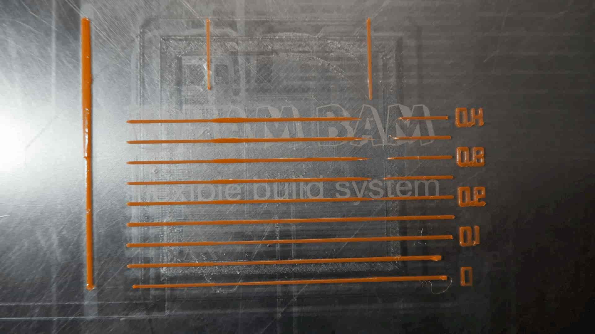
Some of the horizontal lines should have obvious thick and thin portions, and some may even have large gaps. You are looking for the line with the most consistent extrusion width from left to right. The K value for this line will be printed to the right of the line. At this point, as shown in the video, you may wish to repeat the test with a narrower range of values either side of this best K value. This will help determine the best value by using a 'higher resolution'.
With many of the parameters we have tuned so far, we can permanently save them to either the firmware or EEPROM. As the linear advance K factor is filament dependent, this may not be the best solution if you print with varied filaments, and instead you may prefer to save using your slicer profile. All methods are covered below.
The K factor can be set by using the M900 gcode:
M900 K0.11
It can be permanently stored EEPROM by following up with:
M500
Both the setting and saving of the K factor can also be achieved using the LCD menu.
You may prefer to use the M900 gcode command in your start gcode instead, particularly if your slicer supports different start gcodes for different materials. In the event that you use start gcode, unless an M500 follows, the setting of the K factor will be temporary. When the printer is next restarted the value stored in the EEPROM will be restored. When new print starts the value given it its start gcode will overwrite the previously set value.
Linear advance can be temporarily be disabled by setting the K factor to 0:
M900 K0